PUMPS & VALVES
MOTORIZED CONTROL VALVE
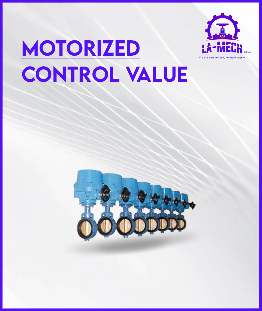
Motorized Control Valve
‘QT’ series electric actuators are designed & engineered for robust, reliable and for high performance duty onto quarter turn valves. The unique reliable motor module, adjustable cam plate limit switch, self locking mechanism, precision gearing system and ball bearings, the auto declutching mechanism, light force load on the hand-wheel, the adaptor drive bushing and bottom ISO 5211 mounting dimension, are added advantages against others in the field of valve automation. CE approved. FM & UL pending.
Features
1.ENCLOSURE
Standard enclosure to water jet proof & water tight proof IP 67, NEMA 4 & 6.
2.MOTOR
Squirrel cage motor is of encapsulated type, on high stall torque and low inherent force for seating & unseating of valves. All motors are integrated with build-in thermal protection..
3.TERMINAL CONNECTION & WIRING
Terminal connections are of “WAGO” push in type, making wiring connection very easy & without fuss. Electrical wiring circuit is standardized for single & three phase voltage. Addition termination is available upon request.
4.INTERNAL COMPONENTS ARRANGEMENT
Internal mechanical and electrical components are designed in modular mounting arrangement, and can be easily removed for maintenance purposes. Addition optional accessories are also possible.
5.LIMIT SWITCHES
A pair of limit switches are activated by means of simple, reliable & adjustable cam plates, mounted directly onto, and driven by center column. The unique cam plate design does not allow over travel of limit switches.
6.TORQUE SWITCHES
Electric actuators on 100 Nm and above, are installed with torque switches for over-load protection.
7.HEATER
For prevention of condensation due to weather & temperature changes, and also keeps intemal components clean & dry, a 20 watt space heater is provided inside all the electric actuators.
8.SELF LOCKING MECHANISM
Because of the worm gear design system, all the electric actuators are self locking.
9.HANDWHEEL
Correct size of hand wheel on the electric actuator ensure adequate strength for safe and efficient emergency operation
10.MANUAL OVER-RIDE
Engage by pulling the lever & turning the hand wheel. Lever is auto declutch when power supply is switched on, and hand-wheel does not turn as extra safety feature.
11.ISIUAL POSITION INDICATOR
The visual position indicator is directly mounted onto the center drive column to provide the visual position of the valve.
12.END STOPPERS
1 each for open & close position (adjustable), are for over travel protection.
13.POTENTIOMETER- optional
Is available on request, is to provide & transmit remote indication of valve position.
14.MOUNTING & ADAPTATION
Bottom flange mounting dimension conform to ISO 5211. A adaptor drive bushing is provided for every electric actuator, is removable and for machining to suite valve stem size.