◔ Operational principle
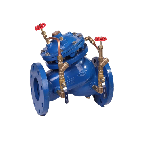
SK760X Slow Shut Control Valve is composed of needle valve, mini strainer and ball valve, etc.
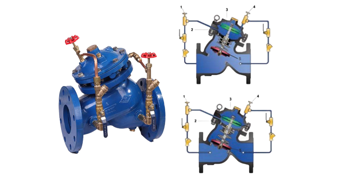
Before the pump starts, there is no pressure before the valve, and disc (5) is closed under the pressure from the spring. With the start of the pump, the pressure before the valve increases gradually. At the same time, the pressure water enters the lower cavity room (2) through the needle valve (1). The two combined force opens the disc of the basic valve rapidly to allow water supply. When the pump stops (as planned or out of accident), pressure before the valve suddenly declines. Pressure after valve exceeds that before the valve. As a result, the higher pressure flows back to the upper cavity room through the needle valve (4) and gets accumulated to drive the membrane down to close the valve disc (5). The pressure within the lower cavity room (2) discharges to the lower pressure area before the basic valve through needle valve (1), which slows down the closing process to prevent formation of water hammer.
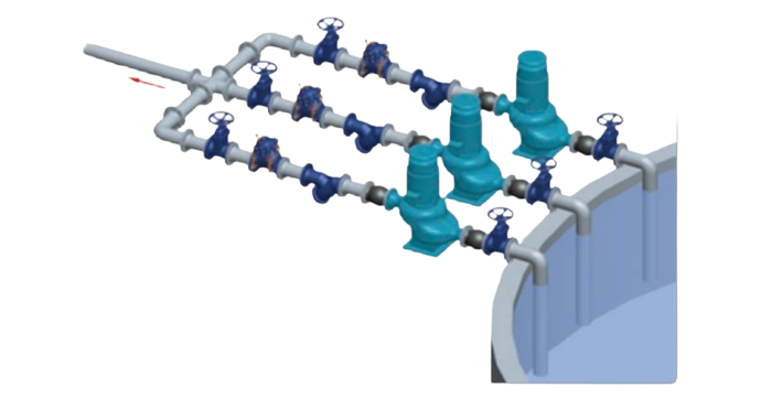
The opening and closing speed of the valve can be controlled by adjustment of the needle valve (1) & (4). For this valve, there is also another option with dual disc design, especially good for working in complicated piping system and working conditions where there is tremendous pressure and water back-flow.
◔ Property and advantages
• Driven by pressure of pipe system, work automatically with energy of pipe system to achieve energy conservation and environment protection.
• Controlled by the pilot valve, lower energy consumption, achieve accurate pressure reducing results, have function of stabilizing pressure after the valve.
• Dual cavity design, with functions of fully opening and fully closing. Slow shut causes no pressure fluctuation, and the diaphragm with support is well protected.
• Have internal orifice, connect bottom cavity and outlet of the basic valve, make sure stability of reaction to keep stability of pressure after the valve, avoid any vibration and noise.
• Channel with straight-flow, slight friction loss, no eddy flow and turbulent flow, cut down the damage of cavitation.
• Long pitch orientation design for stem move, stable and no gap resistance.
• Balanced automatically, big gap design on connection of disc and stem, disc is free on the vertical flat against stem, it can balance the tolerance from machining and sealing surface. Good connection without leakage. Achieve functions of both reducing dynamic pressure and reducing static pressure.
• Ductile iron castings with nodularity higher than 90%, foundry in house with advanced melting technology and strict quality control system, testing reports and testing bars can be supplied with order. Records and testing bars maintained for one year in the factory.
• Good corrosion resistance, with stainless steel, copper alloy, rubber made from DuPont and other rust- resisting material, fusion bonded epoxy coating both for interior and exterior surface of the basic valve. All the characteristics in accordance with ANSI/AWWA C550 and other international specifications like WRAS, NSF61.